Valve Amplifiers

The specification and base pin out left is for an 813 Power Pentode in class C. Photos of my twin 813 amp are shown below.

Its little brother amplifier shown is a 3 x 807 beam tetrode HF power amplifier which has evolved over the last couple of decades. In fact I'm pretty sure that one of the three 807 valves is out of my first transmitter, a No 19 set, purchased from G3WQN in 1970. Output power is about 150 watts on 160m, 80 and 40m.
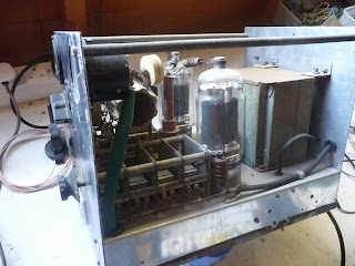


The 813 linear is currently configured as per G2DAF design with step up and rectified input for the screen supply.


One pic shows the 813 beam power pentodes next to a 5u4 rectifier - for size comparison. Between 2kV and 2.5kV is needed on the anode and 400V for grid 2. The pentode construction gives very high gain and in class C (CW) 4 watts input should result in nearly 400W output (each). (ICAS conditions - not current bias cndx). So one in a box could be a nice add on to the FT 817ND.

.

Comments

Popular posts from this blog

GNU Radio Waterfall and CW Filter

The following GNU radio application adds a waterfall spectrogram to the previous CW filter program. The plot show 4 CW signals in the audio band (lower sideband) at 7023 kHz. The 700Hz signal is filtered and output to the laptop headphones by the CW bandpass filter. The frequency display is shown after the script which is as follows: #!/usr/bin/env python from gnuradio import gr from gnuradio import audio from lpf_bpf_class import Bandpass from gnuradio.qtgui import qtgui from PyQt4 import QtGui import sys, sip     class cw_filter(gr.top_block):     def __init__(self):         gr.top_block.__init__(self)           sample_rate = 44100         out_rate = 8000         kaiser = Bandpass()         cw_flr = gr.fir_filter_fff(1, kaiser.bpftaps)         decimate = int(sample_rate/out_rate)         Bandpass.cutoff1 = 3000                pre_decim = Bandpass()         dec_flr = gr.fir_filter_fff(1, pre_decim.lpftaps)         dec = gr.keep_one_in_n(gr.sizeof_float, decima

Digital Bandpass Filter FIR design - Python

The python code generates the Finite Impulse Response (FIR) filter coefficients for a lowpass filter (LPF) at 10 (Hz) cut off using firwin from scipy.  A highpass filter is then created by subtracting the lowpass filter output(s) from the output of an allpass filter. To do this the coefficients of the LPF are multiplied by -1 and 1 added to the centre tap (to create the allpass filter with subtraction). A second LPF is then created with a cutoff at 15 (Hz) and the bandpass filter formed by addition of the LPF and HPF coefficients. The program also generates a test sine wave of a given amplitude and power and to this noise from a Normal distribution is added.  The graph below shows the signal and nois, and the signal (green) after filtering. The input snr is approximately 3dB. The frequency response below shows the passband centered on 12.5 (Hz), the Nyquist frequency is 50 (Hz). from numpy import cos, sin, pi, absolute, arange from numpy.random import normal from scipy.

Splunk Cheat Sheet (Linux)

1. set root's password:  sudo su passwd root Enter new UNIX password: < new_root_password > Retype new UNIX password: < new_root_password > passwd: password updated successfully # su - 2. Remove any existing Splunk directories & create user etc: # rm -rf /opt/splunkforwarder # userdel -r splunk # this will remove as above if user splunk's home directory # groupadd siem # useradd -g siem -s /bin/bash -d /home/siem -m siem # vi ~/.profile # chage -I -1 -m -0 -M -99999 -E -1 siem If above fails because of multiple passwd fails: # pam_tally --reset check with #chage -l siem # uname -a # check OS version # dpkg -i splunk-4.3.1...........intel.deb # chown -R siem:siem /opt/splunk # su - siem : $SPLUNK_HOME/bin/splunk start --accept-license : $SPLUNK_HOME/bin/splunk edit user admin -password newpassword -role admin -auth admin:changeme 3. vi ~/.profile (as follows) (OR .bash_profile) # ~/.profile: executed by the command interpreter for log